Designing and Building a Custom Aluminum Truck Camper Using Onshape
By Jonathan Bruns
This article was originally published on Onshape.com
My partner Losaunne and I like to build things together. We’ve built steel garden planters, pergolas, furniture, and custom cookery.
We also love to camp, backpack, and mountain bike while traveling to new remote places.
On an extended overland trip camping out of the back of a 2004 Toyota Tacoma, we started talking about what was next in life. We liked the freedom to travel and dreamed of building a custom rig that we could live more permanently from.
In the fall of 2020, we drove from Salt Lake City to Rock Springs, Wyoming, to buy a 2002 Toyota Tundra. We planned to fashion a flatbed custom truck camper on the back to live in while we explored remote areas in a kind of mini-retirement.
At that point, there was no CAD model, just hand drawings of interior layouts, and a specification spreadsheet for water, electrical, and various system components.
We had a lot of work ahead of us.
Outlining a Design for a Custom Truck Camper
At that time, I was completing my fifth year as a mechanical engineer at Biomerieux, developing consumables and instruments for PCR-based medical diagnostics. Before that, I received a bachelor of science in Biomedical Engineering from the University of Utah – but got the mechanical engineering and CAD bug from my involvement in a robotics club that competed in an annual NASA Robo-Ops project.
I have been using CAD tools for nearly 10 years, losing my time (and sometimes my mind) more than a few times. I started the initial truck camper design using SOLIDWORKS because it’s what I used at work, but as many engineers and designers know, this can often feel like a black box when communicating the design. Since Losaunne was not a traditional CAD user, it became apparent we needed to both be able to look at the camper designs, so I transitioned the project into Onshape.
After I shared the Document with Losaunne she was able to contribute immediately in a collaborative way. Not burdened with the overhead of traditional CAD was refreshing and allowed us to focus on the design, not the software. We soon had the main ideas of the project outlined in Onshape.
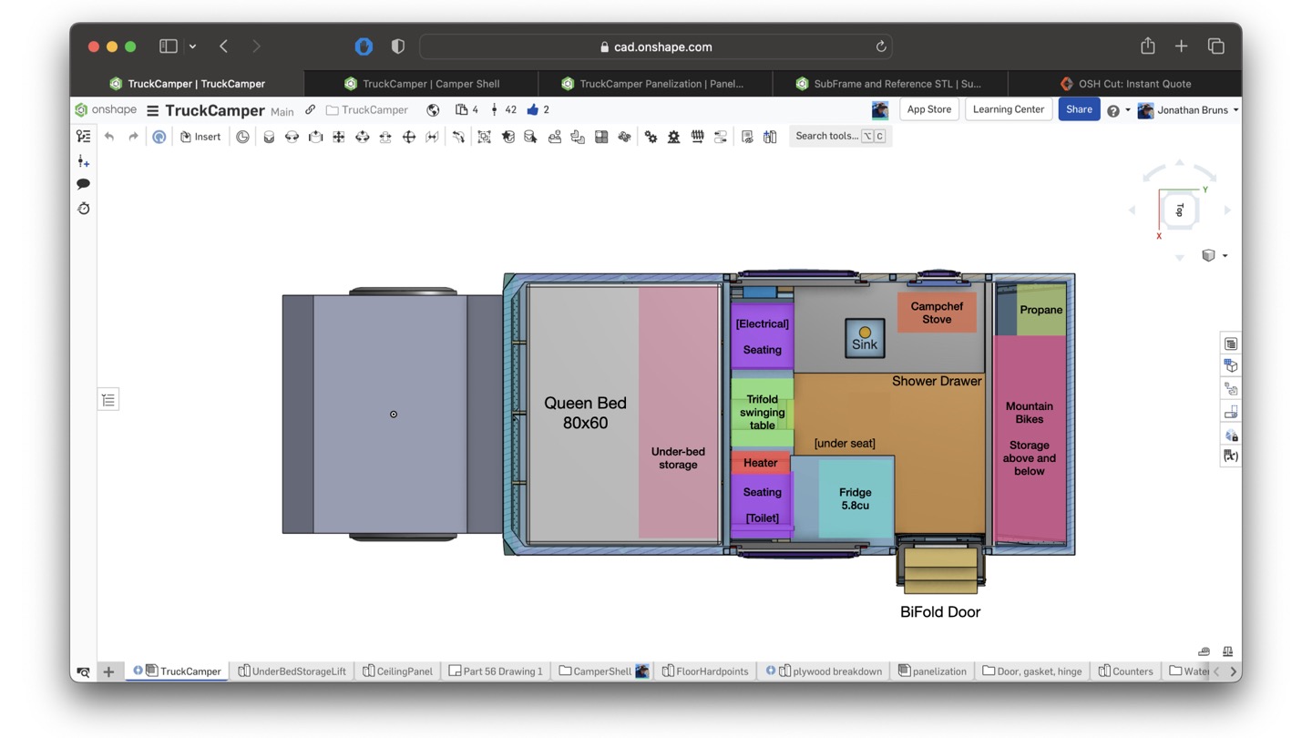
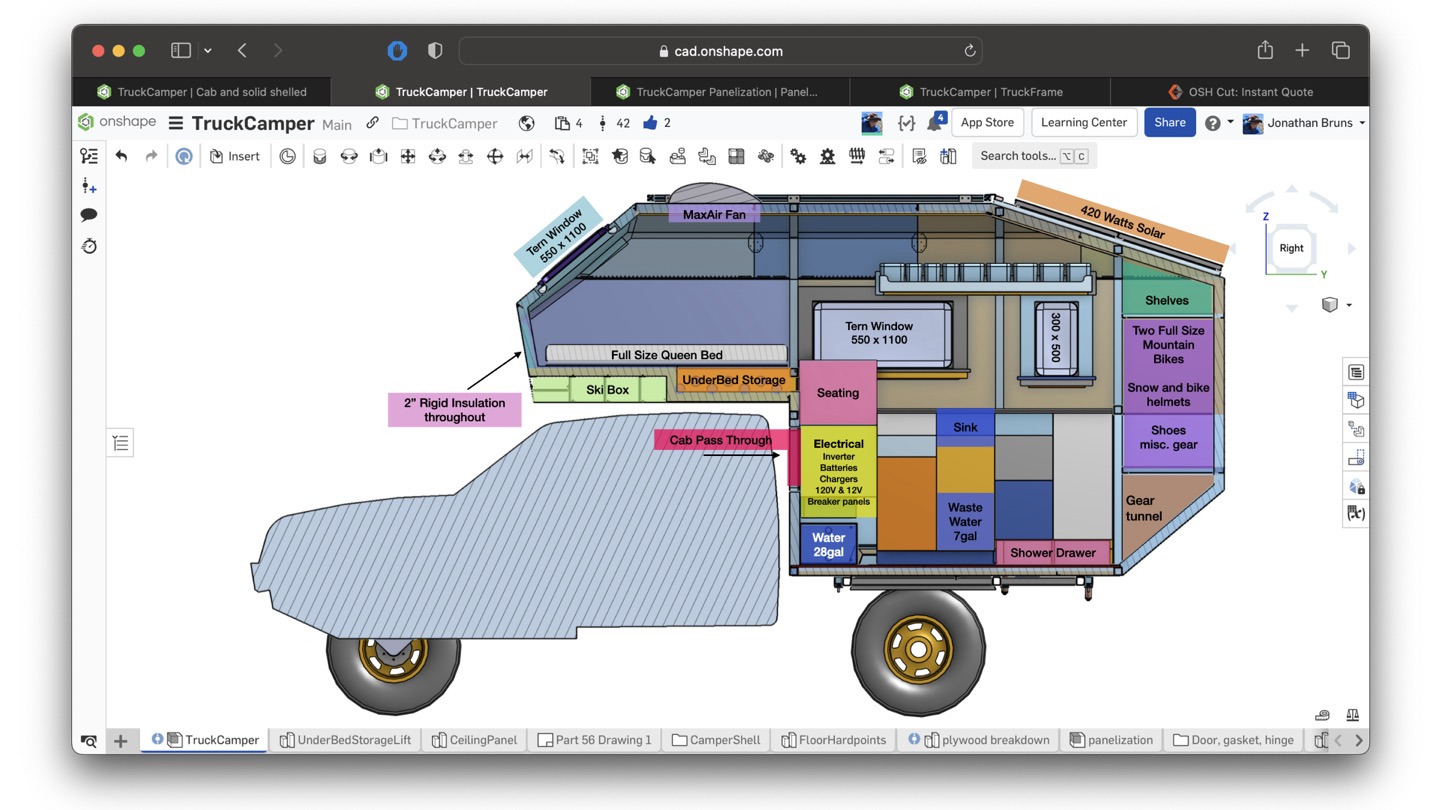
As we were designing the interior, floating various components in/out/around the shell, we had a short list of key features we wanted in the final camper:
- inside storage for two full-sized mountain bikes,
- a locking ski box integrated into the shell,
- maintaining vehicle factory exit angles,
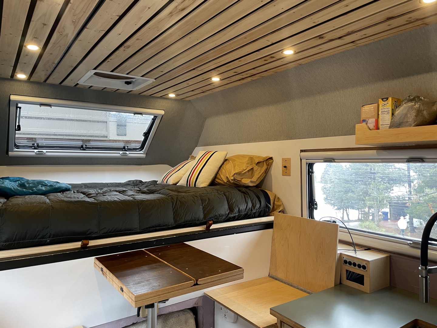
- a queen-sized bed with enough space overhead to sit up,
- storage under the bed,
- cab access/passthrough,
- a large 12V fridge,
- adaptable for both cold and warm weather,
- 25-gallon fresh water storage,
- 2,000-watt gasoline heater, and
- a full solar/electrical system.
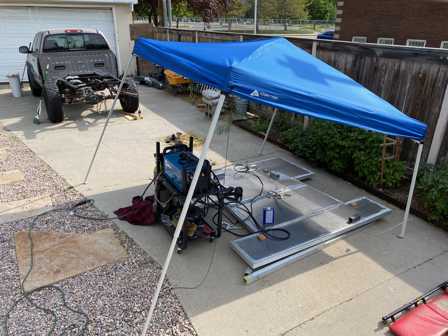
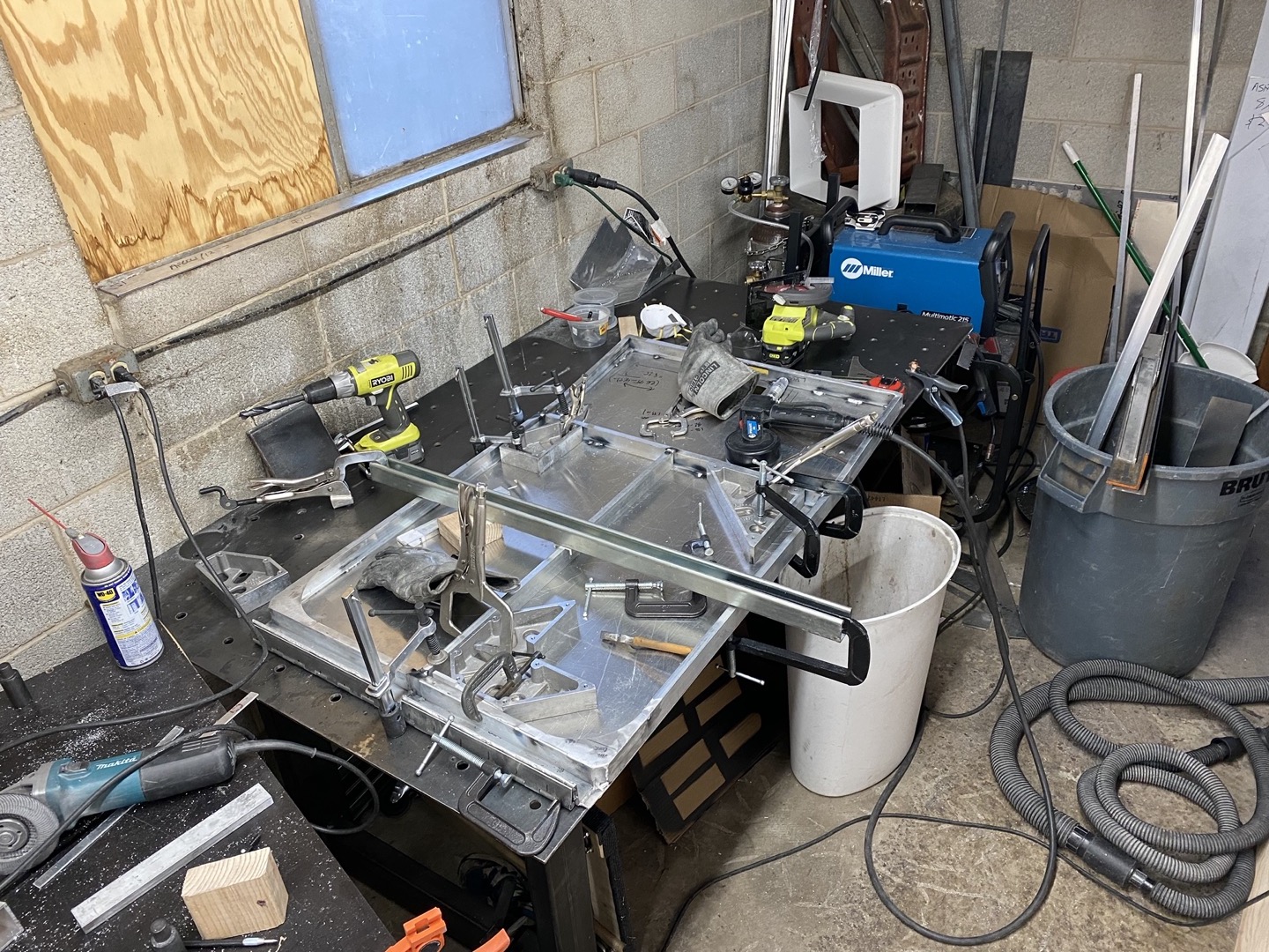
As we started to narrow down the design, it became more and more clear to me that the initial plan to order raw materials and fabricate the shell with shop tools and a welder was crazy.
I started to build the custom truck camper flatbed using this method – and it was working – but it was tricky and time-consuming.
I had previously used a lot of laser-cut aluminum parts at work, and a quip from my old boss and mentor about getting it all laser-cut quickly turned into a serious discussion. I reached out to him and a few old friends from the robotics club for advice and help during various challenges throughout the project.
The laser-cut option for the custom truck camper became more appealing when we started to compare manufacturing costs. Dealing with material utilization, accurate cuts, tolerances – it all starts to add up when a human is doing the measuring and cutting. Even the thought of how to recycle the aluminum scrap after it was cut was daunting. We decided to move to a laser-cut design.
That was an important decision point. This project involved a lot of eating my own dog food – acting as the designer, fabricator, and customer. Putting more emphasis on design and engineering rather than on custom fabrication was a good call. I spent a lot of time reviewing the aluminum sheet metal design before ordering because we were in no position for revisions after placing the very expensive order!
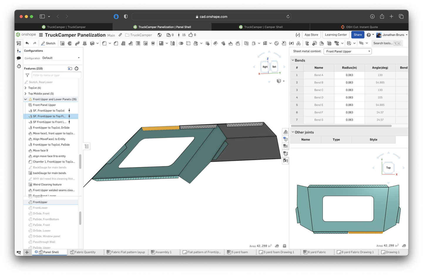
Breaking down the model of the shell design into manufacturable panels wasn’t easy, but the Onshape Sheet Metal tools helped out. Using a 5x10-foot aluminum sheet as a guide for max part size, I started splitting up our outer surface/shell design. I had to think about how this was going to be assembled (on the truck and in the driveway) and wanted all of the pieces to be related to one another so there wasn’t any critical placement needed by those poor fabricators (us). Ultimately I decided on a design with bent interior flanges between the panels, which we would rivet together before welding the outside to achieve the one-piece look.
I roughly split the model into thirds: front, middle, and back, and a top, middle, and bottom. Then I set to thickening a sheet metal model off selected surfaces. The hard part was getting them all related and connected together with rivet patterns and flanges.
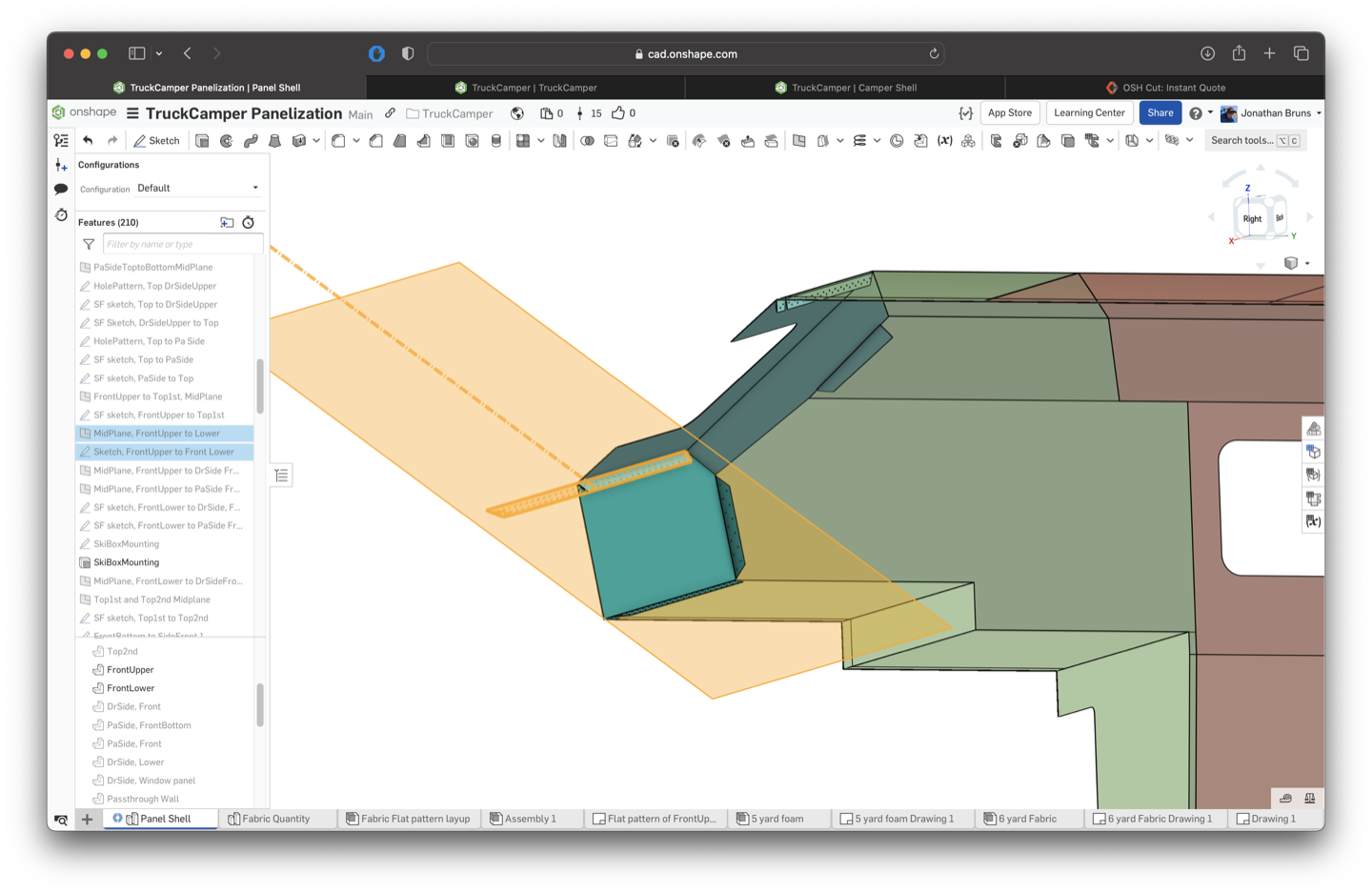
During this process, I was having a hard time making certain shaped flanges and rivet patterns, because the functionality I wanted was missing.
Luckily someone before me had written a Custom Feature Shaped Flange that filled the gap. I was already an Onshape convert, but it was that moment when it really clicked. The Onshape community had developed a specialized feature that allowed me to do something not possible natively, and it blew my mind.
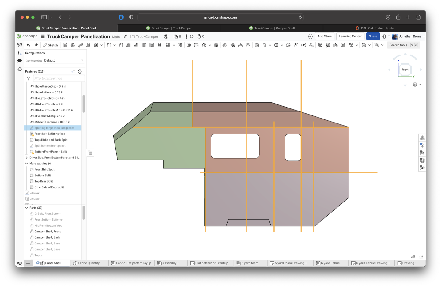
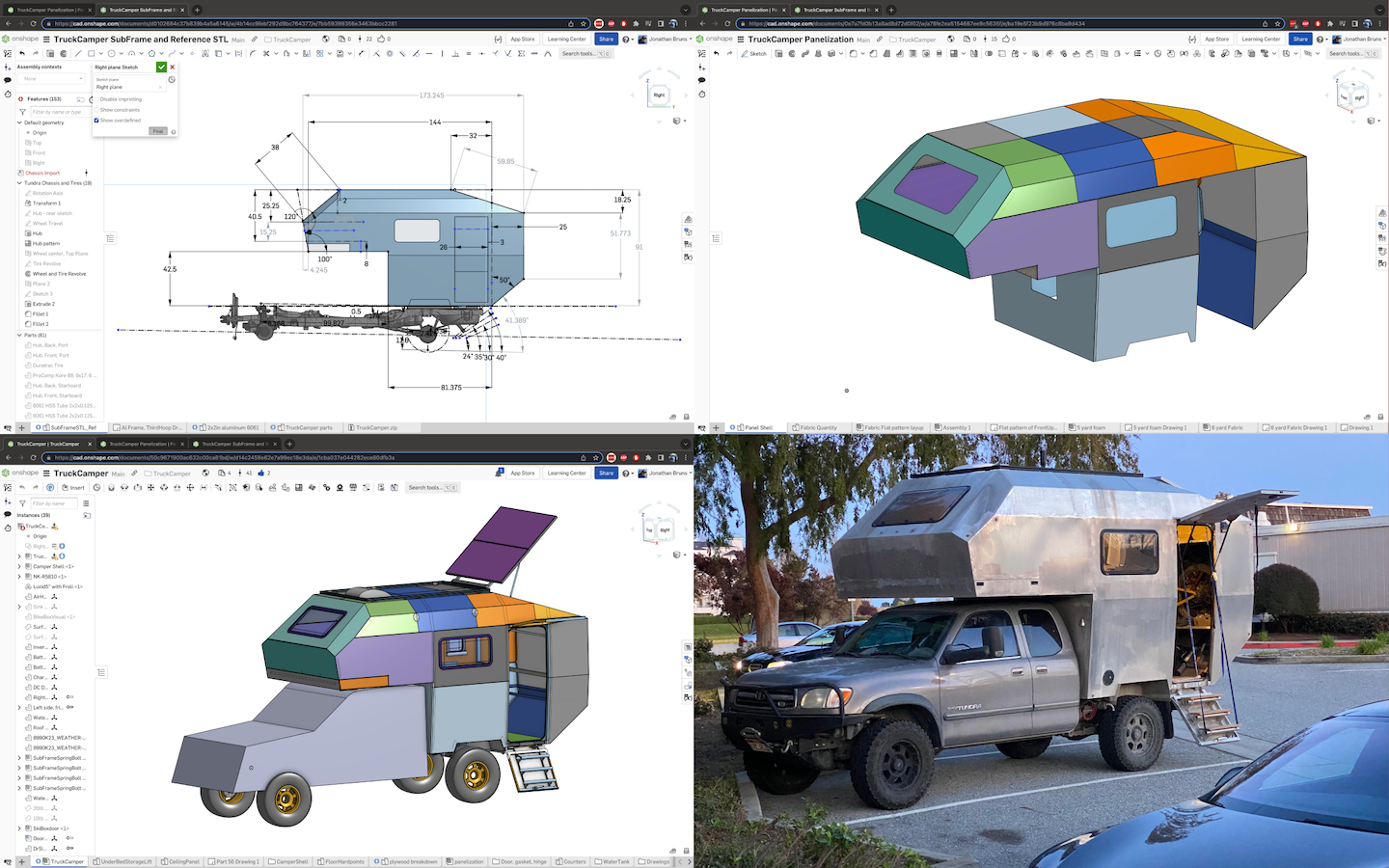
Side view of the model getting split into pieces, top.
flange custom feature highlight, bottom
We used Oshcut, a metal fabrication shop in Orem, Utah, for laser cutting and bending. This was really important because they have an online tool that visualizes the bends in the panel for the designer, highlighting any conflicts with the press brake. Because many of our panels were not immediately manufacturable, I was able to use that real-time feedback to make changes in Onshape and find a solution for all of the panels relatively quickly. We had our parts made out of an 1/16-inch 5052 aluminum sheet and by the time it was getting cut, our order had over 3,000 rivet holes among 36 unique parts.
Designing things with a lot of inter-relations can be tedious. But like the Oshcut quoting tool – Onshape’s dual view for sheet metal design is a game changer. After creating a sheet metal model, the flat pattern can be viewed while simultaneously editing the solid model – allowing for real-time feedback on sheet metal design.
After creating flanges that connected one panel to another, I would check for manufacturability with flat pattern view and Oshcut – and then repeat the process. Most panels have four connections to others, with a matching rivet pattern.
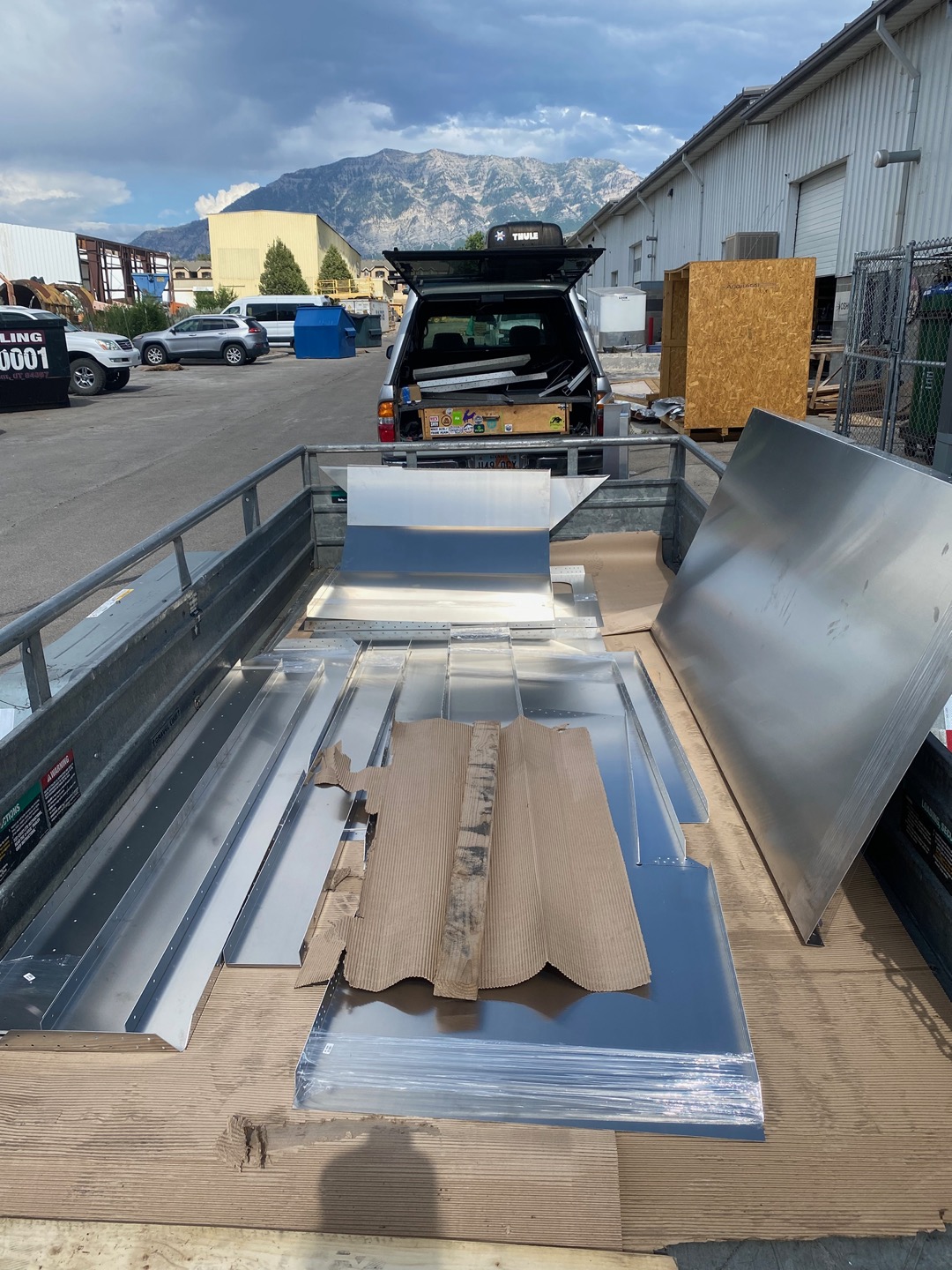
After getting all the kinks worked out with the design, I placed the order and rented a U-Haul trailer to pick up the panels.
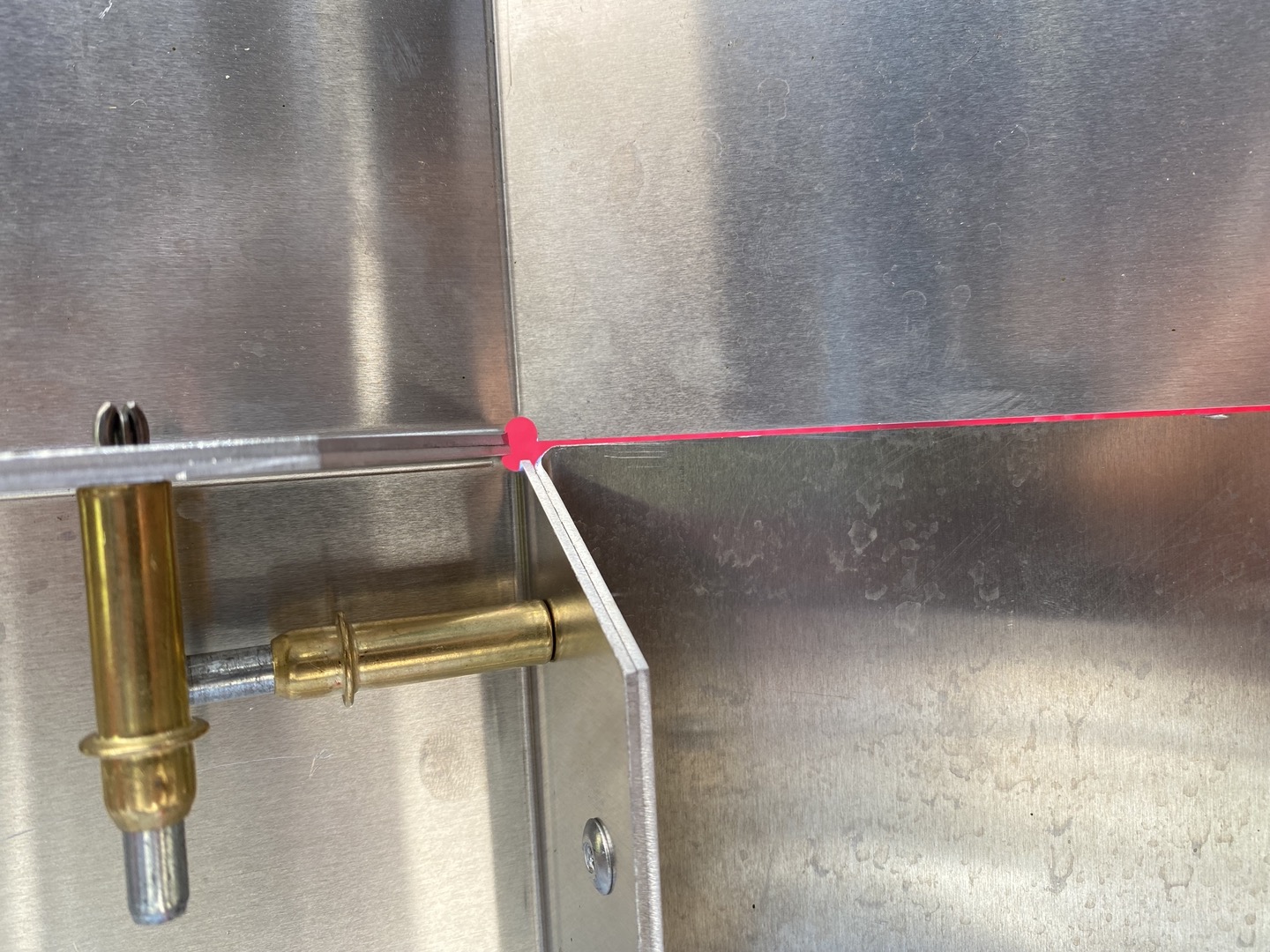
Back home, the parts looked great, but I was nervous to test how well my design had translated into real parts. It was a huge relief when I dropped a 3/16-inch rivet into the first of the 3,000(!!) holes, and saw that the clearance was spot on.
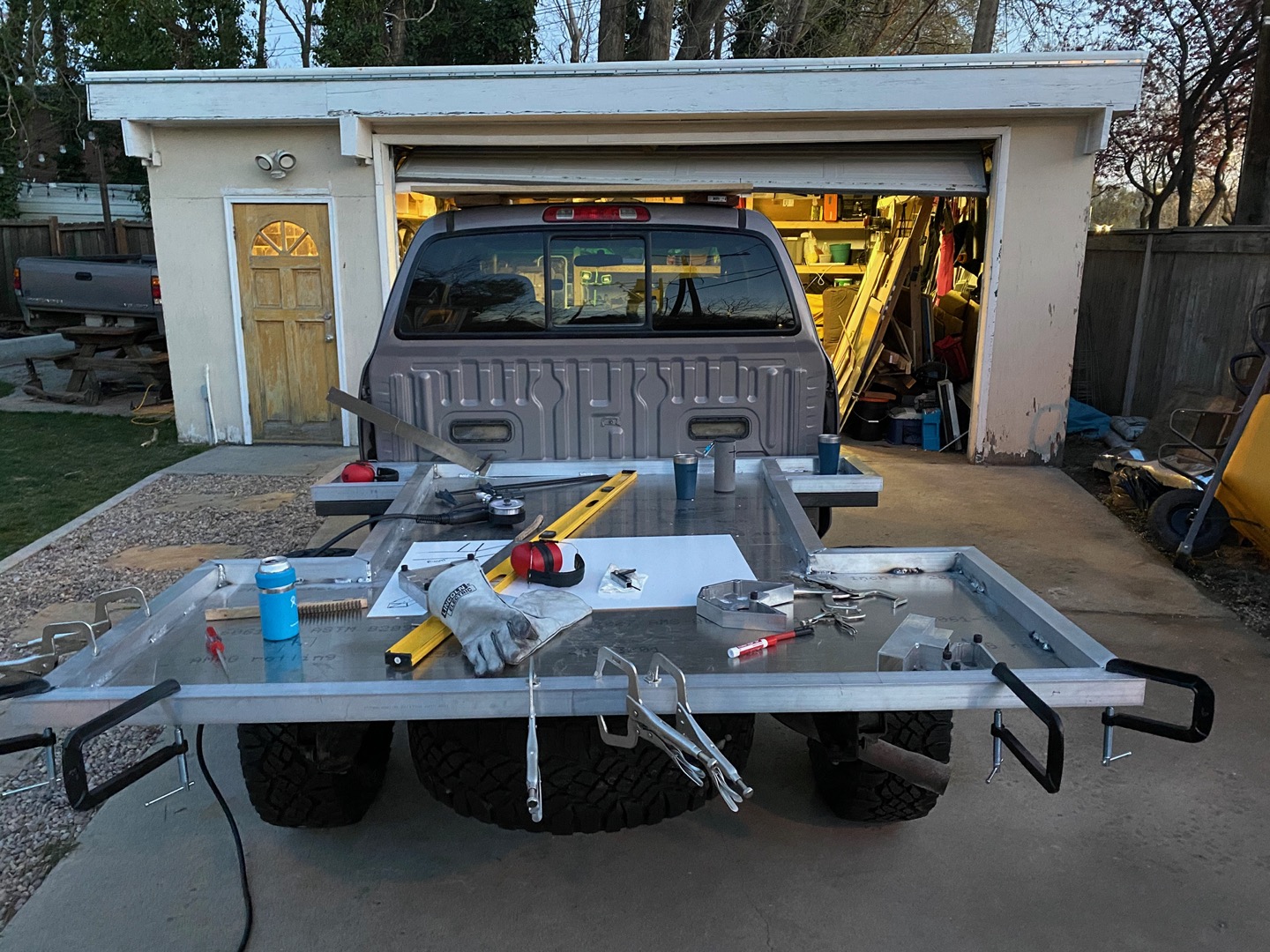
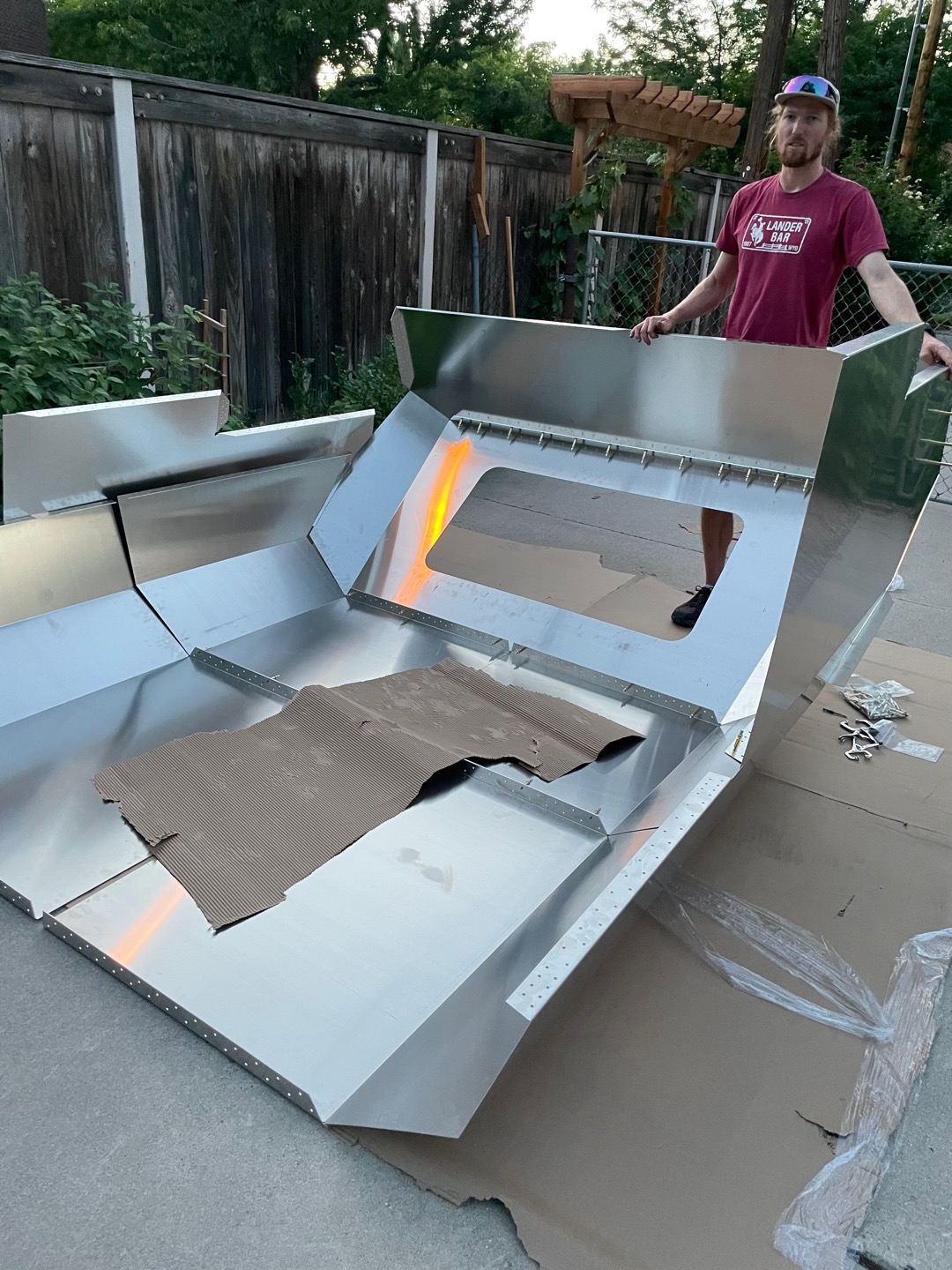
We continued to verify the panels with some rough assembly on the ground, aligning hole patterns with cleco clamps to fit the panels together.
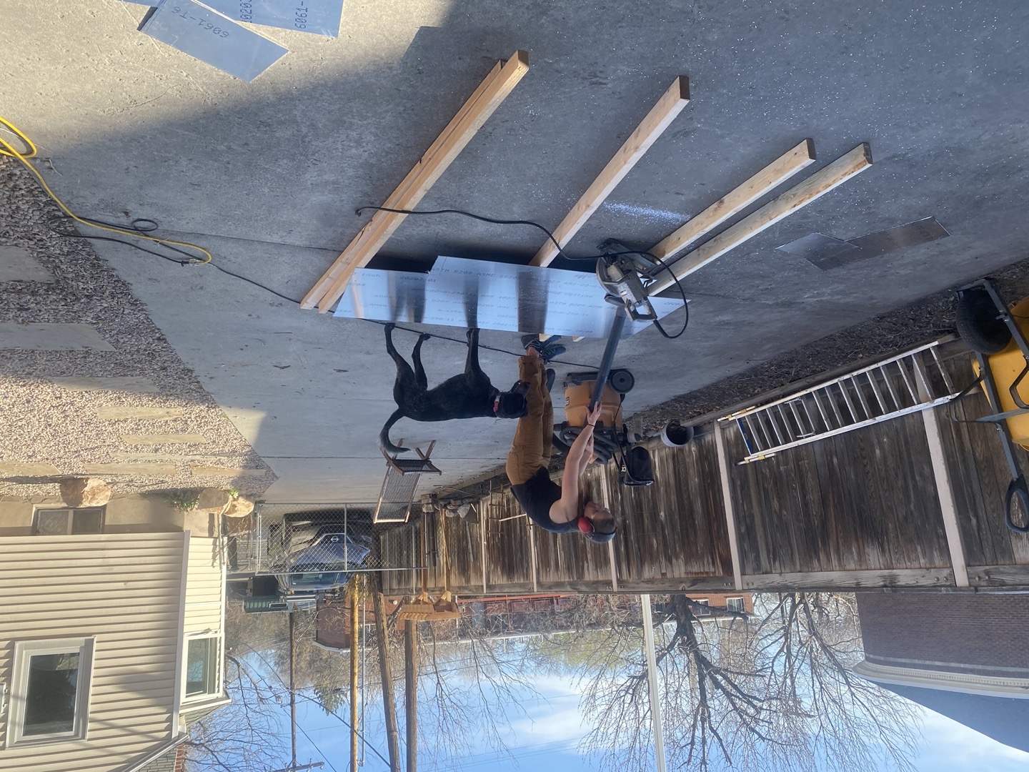
Making the Design a Reality
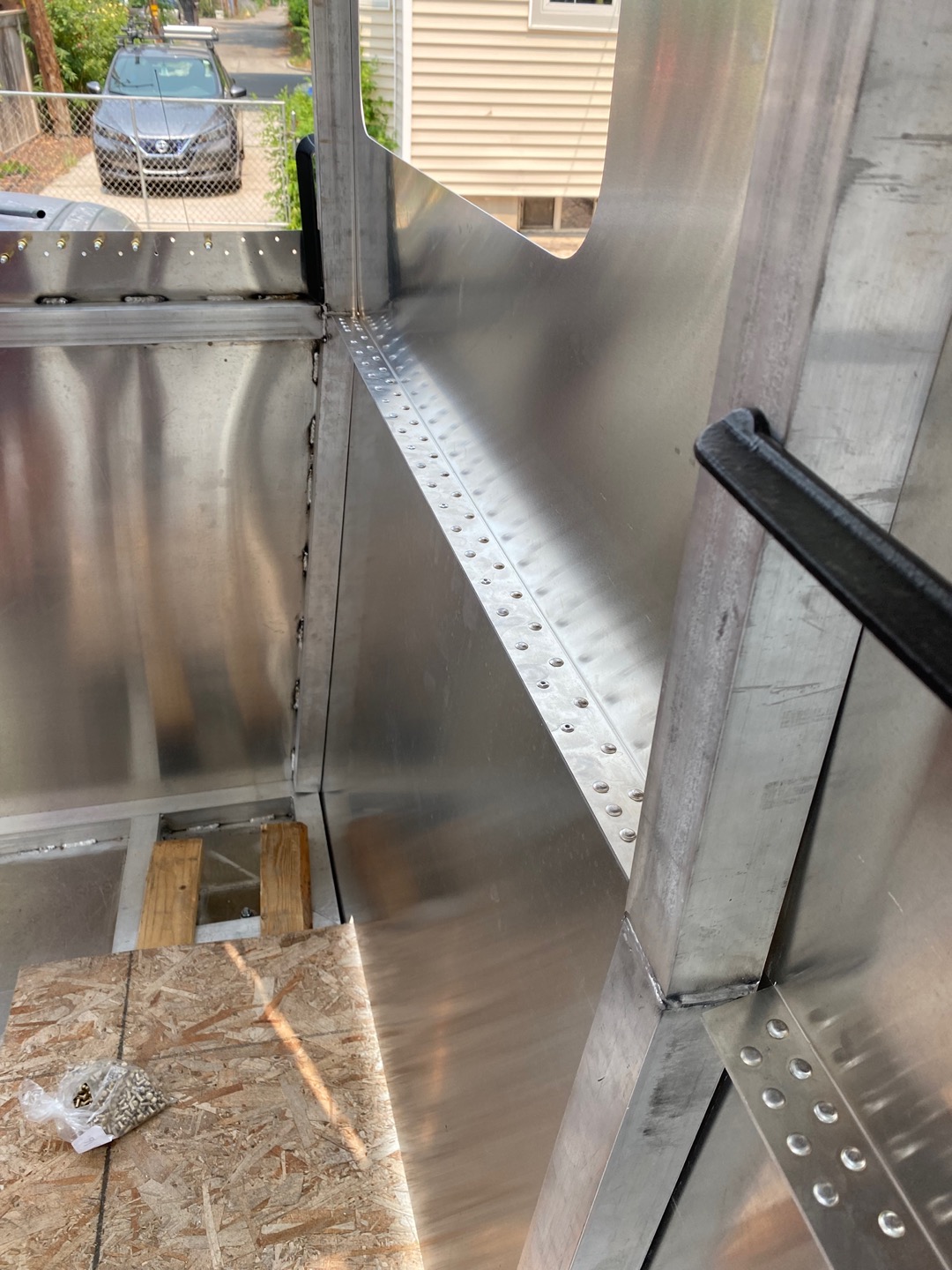
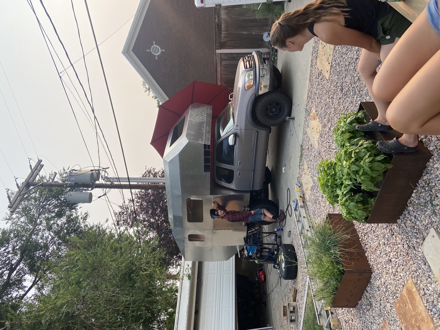
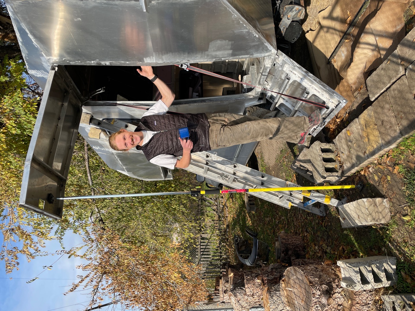
Assembly of the custom truck camper took a lot of time and effort. I leaned heavily into aluminum aircraft building resources, using a pneumatic rivet gun, cleco clamps, and bucking bars for driving solid rivets. We learned techniques for setting solid rivets in tight spots, and how to communicate when the material was between us. Once the shell was completely riveted together, I went back and welded all the seams for a watertight finish, and reinforced the shell with box tube and angle iron.
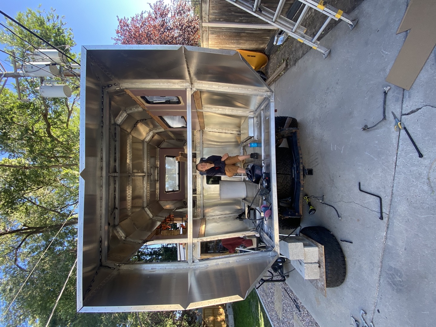
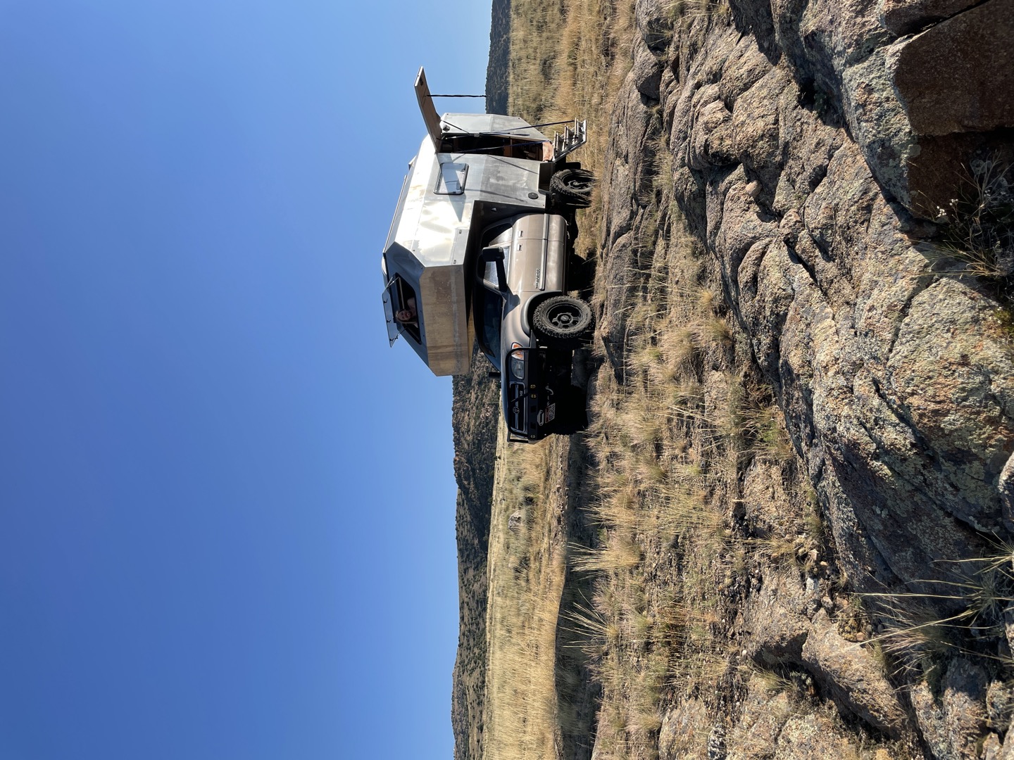
Since we were excited about adventuring and getting on the road, we didn’t fully polish the model to order everything laser cut (although in retrospect, this may have been faster). There were still problems I had to solve, the most difficult being the entry door, which involved getting the right seal, figuring out the hinge points, gas struts, locking and security, and especially managing the strength of the bottom half bifold that functioned as stairs. There is a certain satisfaction that comes from building your own design, but also a lot of humble pie!
There were other smaller projects in which I was now acting as a fabricator, including the stairs, underbed storage, ski box door, cabinets, and other non-shell-based items.
For these projects, I turned more and more to the iOS version of Onshape on my phone to check dimensions, measure things, and make modifications so my fabrications stayed in sync with the CAD model.
Lessons Learned and Reflection
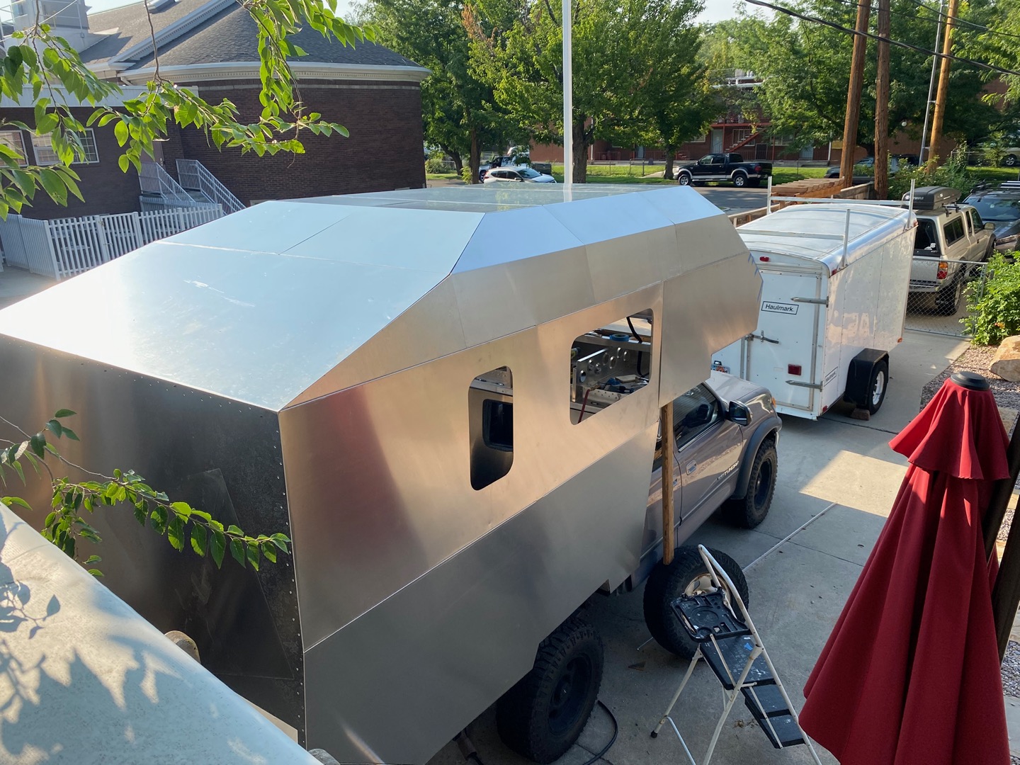
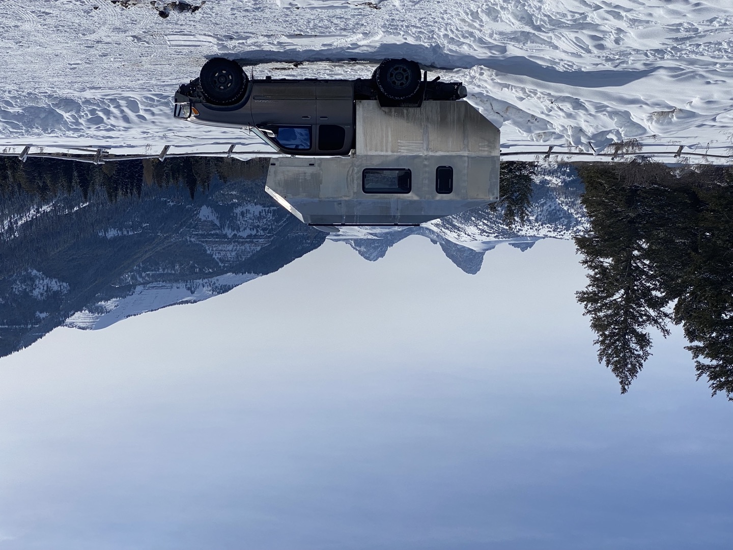
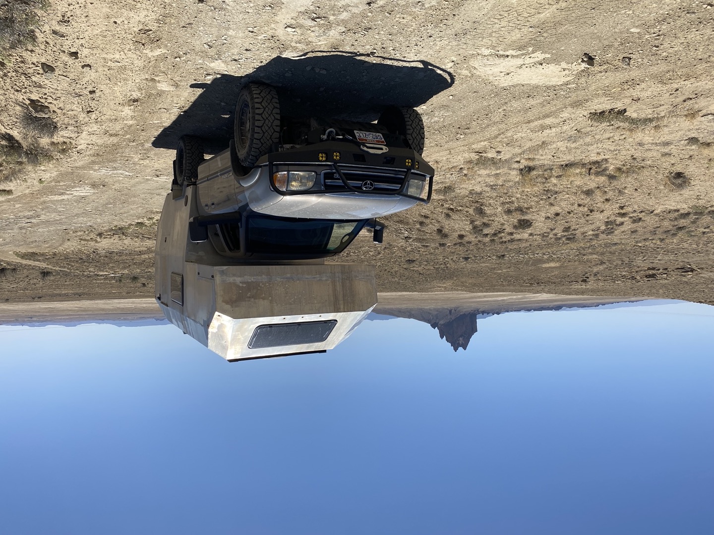
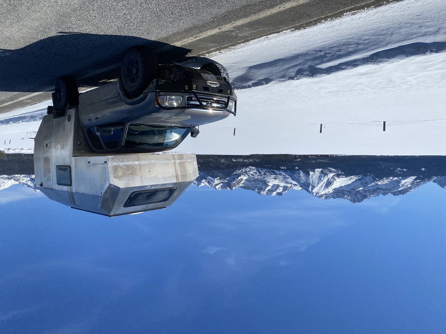
It took us about four months of design time, and then about four months of building before the custom camper truck was drivable. It was a glorified box with windows then – but quickly became a second home.
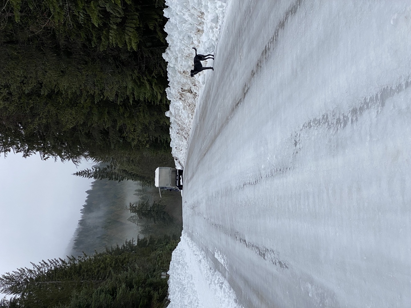
As we progressed through the build process, we began testing it on trips at various milestones. So far, we’ve learned some important lessons about our design:
- Do not put the camper entry door on the driver side.
- Instead of a sink drawer, an in-floor sink that doubles as an entry mat is more functional/practical.
- Use laser cut and riveted columns in place of welded box tube.
- Flanges meeting in the flats of the panels would be easier to rivet together.
- Plan out access for systems, our design buries the heater and water.
- Thermal break between the box tube and inside could have been better than we planned
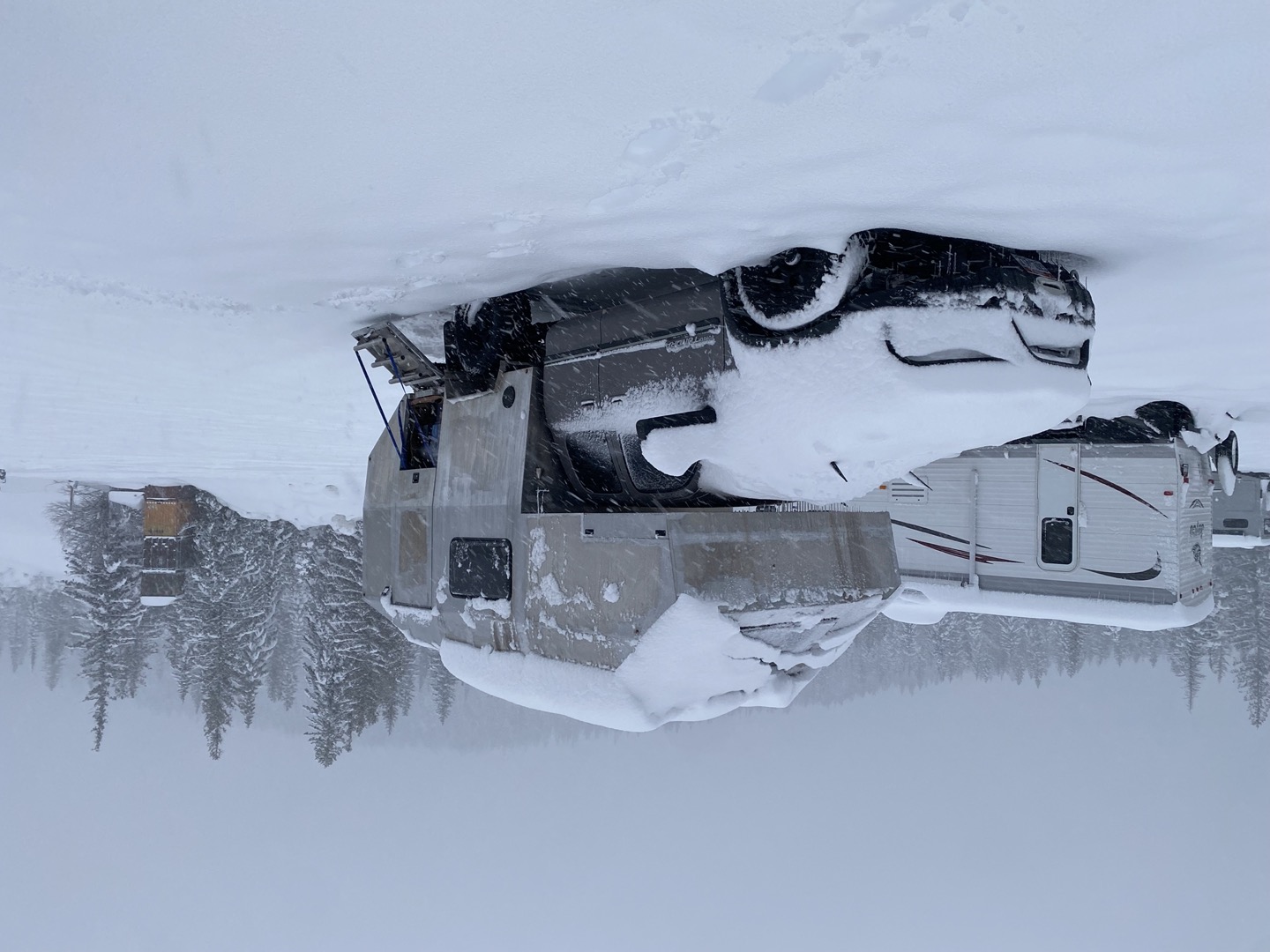
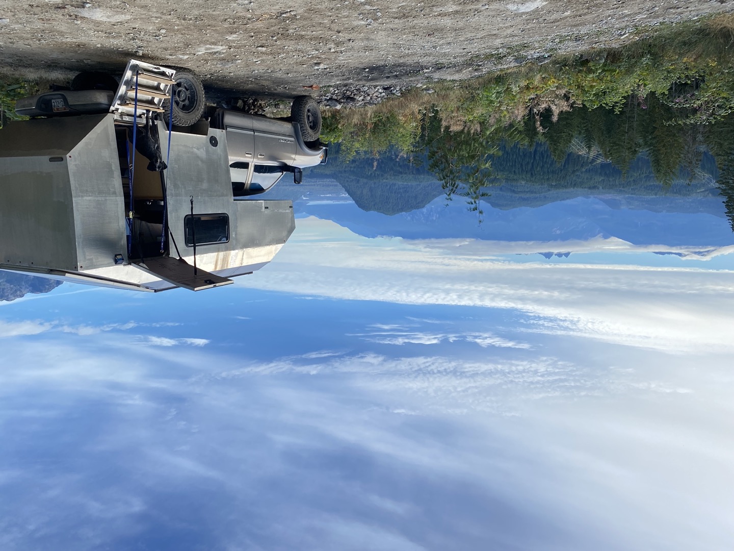
As we put more miles on the rig, we had to balance upgrading vs. using it for fun trips. So far, we’ve clocked 27,000 miles in the camper, taking it to 16 western states, as far east as the Upper Peninsula of Michigan, plus the Canadian provinces of Alberta and British Columbia.
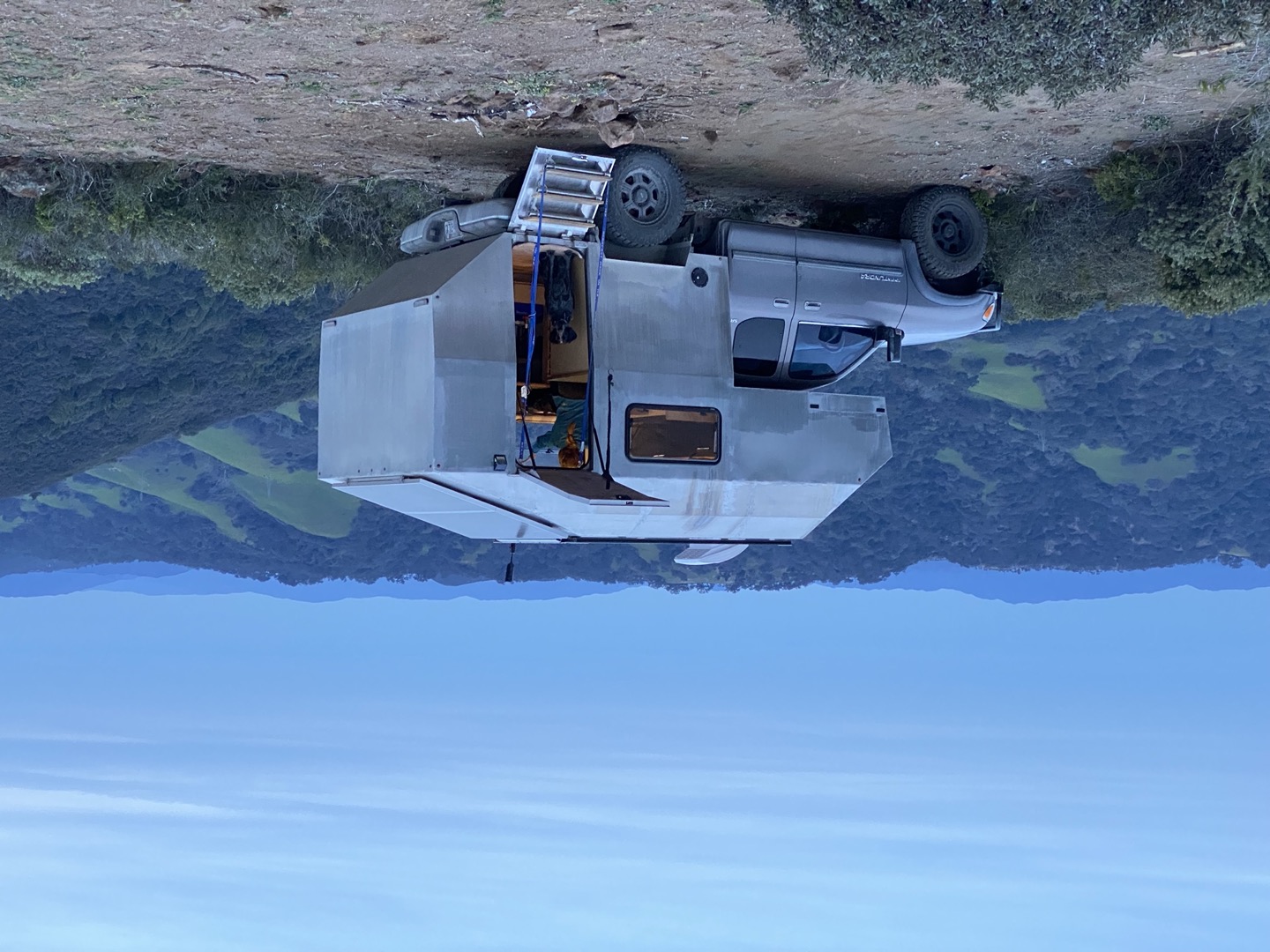
As we continue to adventure, modify, and build (it never is done!) – one thing has become very clear: It is super satisfying to build your own custom truck camper but at the same time the tools you use matter!
Having used Onshape extensively for this project I recommend it for both professional and personal use – whether you're familiar with CAD or not – having full-scale CAD just a login away is the new future. So jump on in!